
2. Typical installation of firefighting units with vertical turbine pumps
The fire pump is a crucial element to a building's fire sprinkler system. Fire pumps are typically made with no-corrosive internal parts to avoid clogging due to corrosion. To avoid cavitation and to have a stable system pressure, the fire pumps are designed specifically for adequate water supply purposes, with strict requirements.

Fire Pump Connection Diagram Photos Cantik
A factory-built integrated fire pump unit consisting of pump, driver, and variable speed control unit, configured to maintain the set pressure until the maximum power draw is reached while acting as a variable speed pressure limiting control and/or a variable speed suction limiting control. Design Envelope Fire Pump Unit Conventional

Aurora Packaged Fire Pump Systems Fox Valley Fire & Safety
Electrical systems for fire pumps are governed specifically by NEC Article 695. This article includes all of requirements for normal and alternate sources of power for fire pumps.
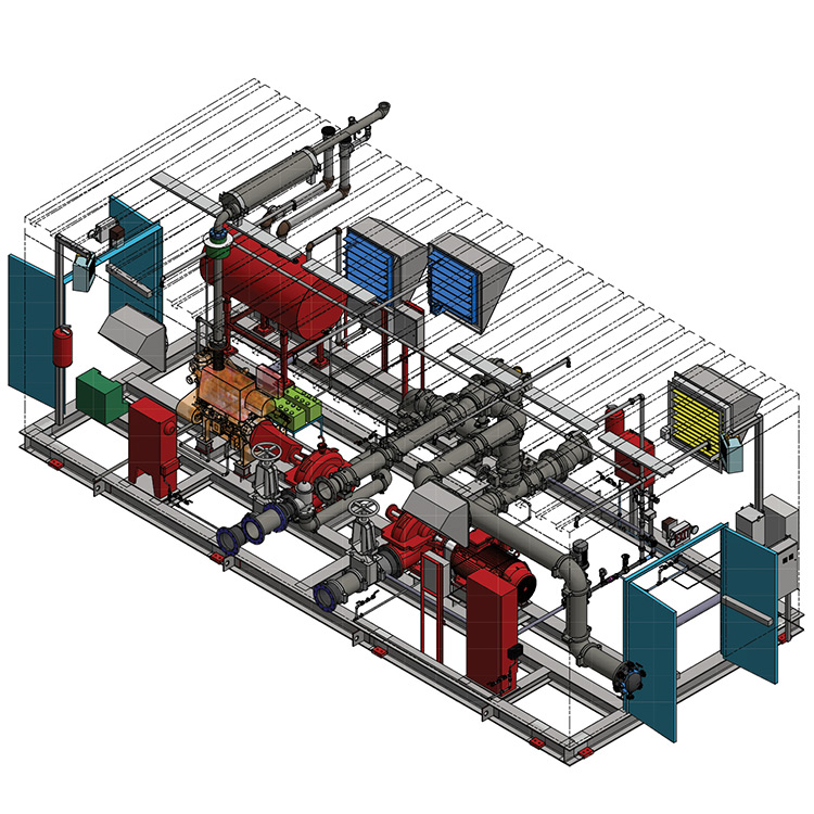
NFPA20 compliant Fire Pump House
The items below serve as a basic checklist of additional coordination items not previously discussed. Points on the fire protection system monitored by the fire alarm system such as fire pump status, control valve positions, waterflow and tamper switches. The approved audible alarm device required per IBC 903.4.2.
Aurora Packaged Fire Pump Systems Fox Valley Fire & Safety
NFPA 20: Standard for the Installation of Stationary Pumps for Fire Protection protects life and property by providing requirements for the installation of fire pumps to ensure that systems will work as intended to deliver adequate and reliable water supplies in a fire emergency.

PJH Fire Sprinkler Design, L.L.C. Sample Drawings
5. INSTALLATION Fire water pump sets and control systems should be installed, and accepted, in accordance with NFPA 20. Failure to install the supplied NAFFCO fire pump set fully in accordance with the NFPA 20 will void the equipment warranty. Proper ventilation and drainage system shall be provided for fire pump room. 5.1. Foundation

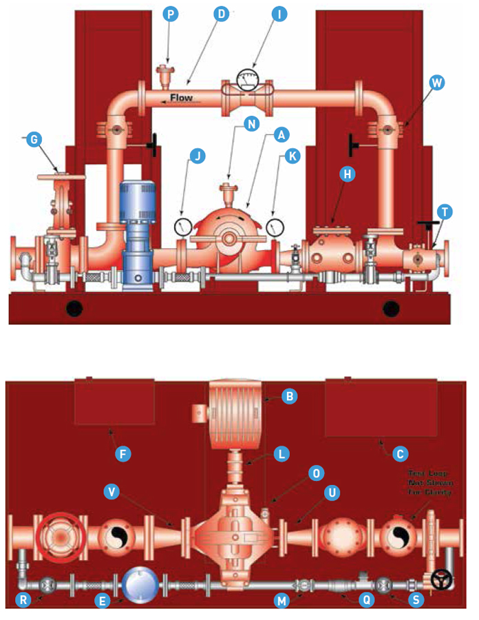
Fire Pump Schematic Diagram
1- Gate valve 2- check valve 3- Suction header 4- Discharge header 5- Diesel pump 6- Jockey pump 7- Electric pumps 8- Pressure relief valve 9- Alarm check valve 10- Water flow meter 11- Diesel pump electric control panel and pressure sensing line 12- Jockey pump electric control panel and pressure sensing line
METHOD STATEMENT FOR INSTALLATION AND INSPECTION OF FIRE FIGHTING
The primary design references for fire pump installations are NFPA 20 Installation of Centrifugal Fire Pumps, Unified Facilities Criteria (UFC) 3-600-01 Design: Fire Protection Engineering for Facilities. The Designer will coordinate this specification section with any applicable contract sprinkler system.
Fire Pump Installation Fire Protection Florida Sprinklermatic
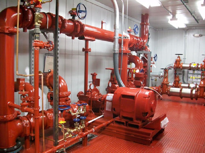
For this blog, we feature an installation in Phoenixville, PA, installed by H & H Systems, Inc. The installation is of a Peerless horizontal split-case fire pump, along with controller, jockey pump, and accessories. As with many new installations, there is not a lot of space in this particular mechanical room.

Key Considerations in Fire Pump Design and Installation
Aug 11, 2023 Share: Installing a fire pump properly is essential to ensure its reliability and effectiveness during emergency situations. Below is a general guide for fire pump installation, but always refer to the manufacturer's specific installation instructions and any relevant local codes and regulations: Pre-Installation Preparation:

Complying with fire pump standards Pump Industry Magazine
1.0 Installation 1.1 Location and storage 1.2 Foundation for hsc pump 1.3 Pump mounting and piping 1.4 Alignment 1.5 Minimum fittings 2.0 Operation-electric driven 2.1 Prestart-up 2.2 Pressure switch setting 2.3 Circulation relief valve 2.4 Start-up procedure Electric driven Diesel engine driven 2.5 Automatic operation 3.0 Maintenance
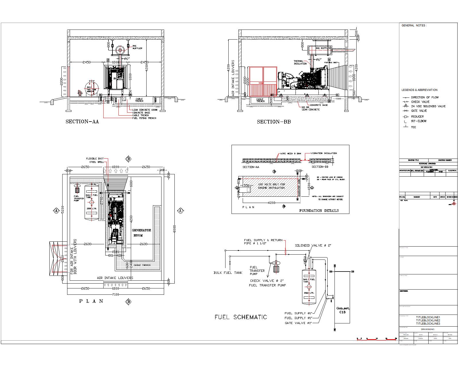
Standard Fire Pump Generator (mechanical) CAD Files, DWG files, Plans
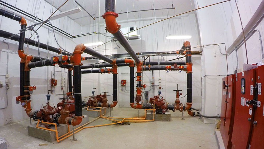
Fire pump intakes are connected to underground public water supply piping, or a tank or reservoir located onsite, to provide water flow at a higher pressure to the sprinkler system risers and hose standpipes. Fire pumps are activated when the water pressure in the system drops below a certain threshold.

Fire Fighting Pump Connection Details & Its Working. YouTube
Installation and maintenance clearances. Clearances for energized electrical equipment per NFPA 70 (National Electrical Code). Proper orientation of the pump relative to the suction piping to ensure established minimum distances to parallel fittings.

Fire Pump Installation in NH & CT Fire Pump & Sprinkler Installation
Centrifugal Fire Pumps: Centrifugal fire pumps are widely used due to their efficiency and reliability in supplying water to fire suppression systems. Our experts are well-versed in the installation of centrifugal fire pumps, ensuring proper alignment, piping connection, and integration with the existing fire protection infrastructure.

Fire Pump installation Details Main Pump Jocky Pump DG Pump
1. A circuit breaker designed for installation in a normal power supply circuit, upstream of thecircuit breaker in a fire pump controller (see diagram 2) should be selected with aninstantaneous trip setting at 21 times of the full-load current and with thermal/locked rotorovercurrent protection setting at 350% of the motor full-load current. 2.

fire pump installation details YouTube
A fire pump is any type of purpose-driven pump used within a fire protection system. It can be driven by diesel engines, electric motors or even steam and is used to provide increases in water pressure to meet the design requirements of a fire protection system. Fire pumps do not create a water supply.