
Rib2401d Wiring Diagram Free Wiring Diagram
Relay Wiring Diagram What is a Relay? As mentioned earlier, a relay is essentially a switch. Unlike a traditional switch, which we flip or toggle to make it ON and OFF, a relay is an electromechanical switch. The 'mechanical' action of moving the switch between ON and OFF positions is achieved by an 'electrical' signal.

5 Pin Relay Wiring Diagram Use Of Relay
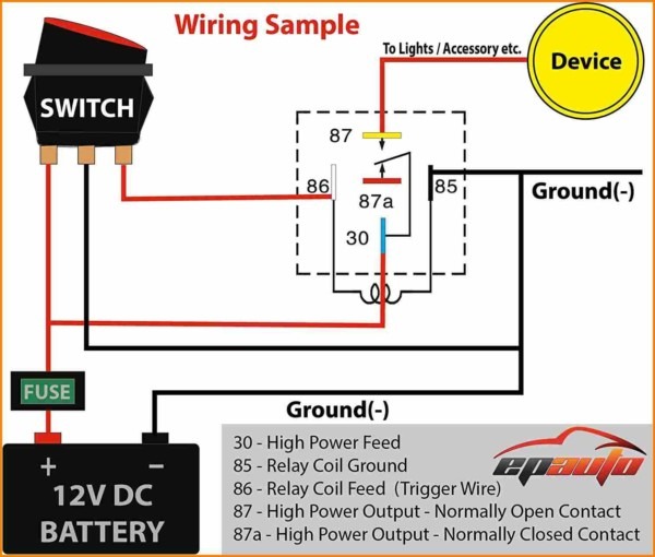
5 Pin Relay Wiring Diagram. A 5-pin relay can control two devices based on the switch position. When the light switch is off, the second device is on by default(NC position). When the relay is activated(the light switch is on), the second device turns off, and the first device turns on. See the wiring diagram of a 5-pin relay below in both.
How A 5 Pin Relay Works Youtube Relay Wiring Diagram 5 Pin Wiring Diagram
QUICK TIP: This is a portion of my larger "Relays Explained" video. In this quick tip we look at how to wire a 12V Automotive Relay.See the full video here:.

Altronix Relay Wiring Diagram Free Wiring Diagram
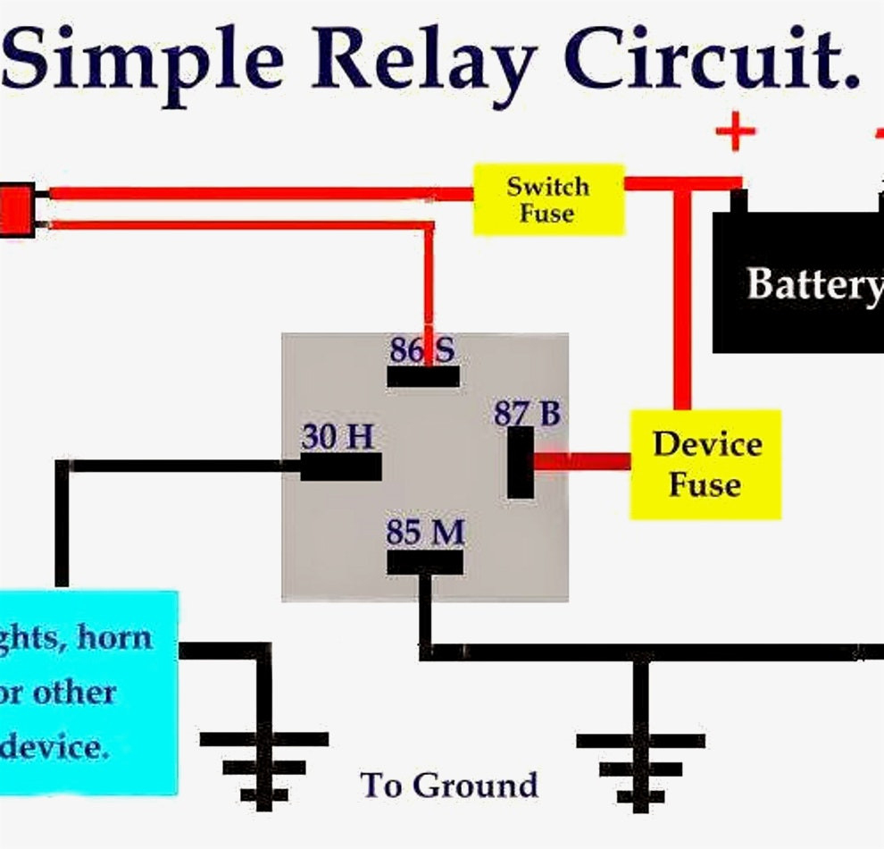
Steps for wiring a relay The relay will connect to three other components in the circuit: A power source A controller, such as a switch The load to be controlled Follow these steps: Step 1: Check the Wiring Diagram 12V relays normally have a wiring diagram printed on them like the one below to ensure you make the connections properly.

12+ 6 Pin Flasher Relay Wiring Diagram Robhosking Diagram
This is a video tutorial on how exactly to wire a relay, how it works, why you would want to use one, and a demonstration in a practical application. By the.

Siemens Overload Relay Wiring Diagram Free Wiring Diagram
The relay contacts open to their normal state and stop the current flow to the light. Once you let off of the STOP button the circuit is back to it's normal state with L1 waiting for the START button to be depressed. There you have it. A relay circuit. Now these diagrams are known as relay logic or ladder diagrams.
30 40 Amp Relay Wiring Diagram Manual EBooks Relay Wiring Diagram Wiring Diagram
1.5K Share 53K views 11 months ago Automotive Wiring How-To's *PARTS LIST IN DESCRIPTION BELOW* 5 pin relay wiring can be done many different ways. The two most common ways to wire a 5 pin.
How To Wire A Relay Electrical The Mini Forum
Relays are a mechanical device that can connect or disconnect power to an accessory when it gets a low voltage 'signal' from a switch. Some people may ask why they should bother using a relay when you can just wire an accessory directly through a switch to its power source. There are two main reasons why relays are utilized:
Bosch Relay Wiring Diagram 5 Pole Manual EBooks 5 Prong Relay Wiring Diagram Cadician's Blog
Published on: June 17, 2022 7 min read Contents By definition, a relay is an electricity-operated switch. It is used in electronic circuits to regulate and control multiple operations. With the help of a relay, you can control a high current circuit via the setup of a low current circuit.
Gallery 5 Prong Relay Wiring Diagram Fresh 4 Pin Electrical Outlet 5 Prong Relay Wiring
Want to Design a Relay Wiring Diagram? EdrawMax Circuit Diagram Maker is able to create circuit diagrams and more electrical diagrams, as well as wiring diagrams in minutes. Give it a try! Switch to Mac > Try It Free Here is the most comprehensive guide you can learn about relay wiring diagrams.

Relay Wiring Diagram For Dual Fans
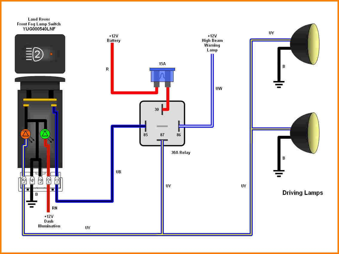
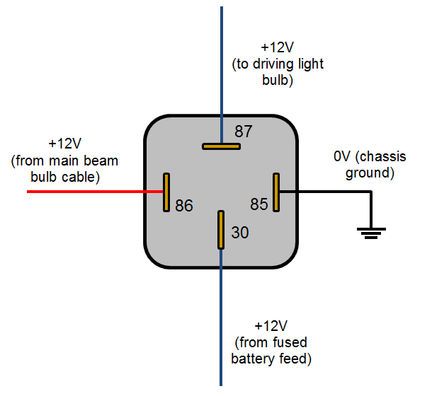
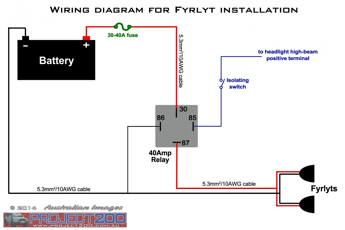
The following diagrams show some common relay wiring schemes that use 4 pin ISO mini relays. 1. Adding driving lights that come on with the headlight main beam: This simple circuit uses the power feed to the headlight main beam bulb as the trigger to energise a relay. The high current circuit in this relay feeds power to the driving light bulb.

[DIAGRAM] 3 Pin Horn Relay Diagram Wiring Schematic FULL Version HD Quality Wiring Schematic
It is commonly used for controlling lights, fans, motors, and other electrical devices that require a higher current to operate. When wiring a 12 volt relay, it is important to follow the schematic diagram provided by the manufacturer. This diagram shows the connections and components required to properly control the relay.
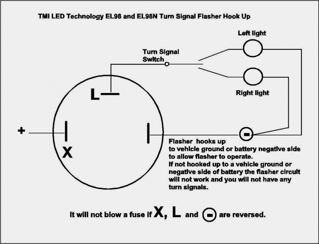
2 Pin Flasher Relay Wiring Diagram Wiring Diagram
A 12 volt relay wiring diagram is an essential tool for any electrician or automotive enthusiast. It's important to know how these diagrams work before attempting to wire up your own relay. When wiring a 12 volt relay, there are several points to keep in mind. First, the diagram should include a power source, such as a battery, which will.
How To Wire A 5 Prong Relay
Select a relay diagram or choose from the list below. (76 relay diagrams available) Relay Wiring Diagrams (Last Updated: 5/4/2020) 1 Connecting Additional Devices to the Remote Turn On Wire 2 Constant to Momentary Output - Negative Input/Negative Output 3 Constant to Momentary Output - Negative Input/Positive Output 4

Relay Wiring Diagram and Function Explained ETechnoG
[1] If you're unsure you have the right relay, confirm what type you need at a car dealership, auto shop, or with a mechanic. [2] Confirm whether you need an SPST or SPDT relay and whether the large circuit needs to be normally open (NO) or normally closed (NC) when the relay is at rest.

50732 Relay Wiring Diagram
This diagram shows the number and locations of each pin so that you can ensure you're attaching the relevant wire to the correct pin. Browse All Relays How to Wire a 4-Pin Car Relay A 4-pin relay is a simple structured relay. The pin numbers on a 4-pin relay are 85, 86, 87 and 30.